Goal
Building a new monoband antenna which I'll orient in the opposite direction (east-to-west) to my other multi-band 80m Off Center Fed (OCF) Dipole that's installed in a north-to-south orientation on my property.
Height will once again be a challenge as I just don't have the trees or towers required to reach an optimal height for a 20m dipole of 42 feet. Instead, I'll have to live with 25 feet as that's the max height of the trees, ropes, and pulley's that I put up last year. The good news is trees grow, but I suspect I don't have the patience for them to reach 42 feet as part of their natural growth.
What happens when a dipole is installed lower than the spec, it's radiation pattern angles higher towards the sky, this affects the range of the antenna since the signal transmitted will point more upward than towards the horizon. But my other off-center fed dipole is also lower than I'd like and I get plenty of decent contacts from that antenna, so I'm ok with the compromise.
Ingredients
- Laundry line cable with clear plastic coating (salvaged from antenna project)
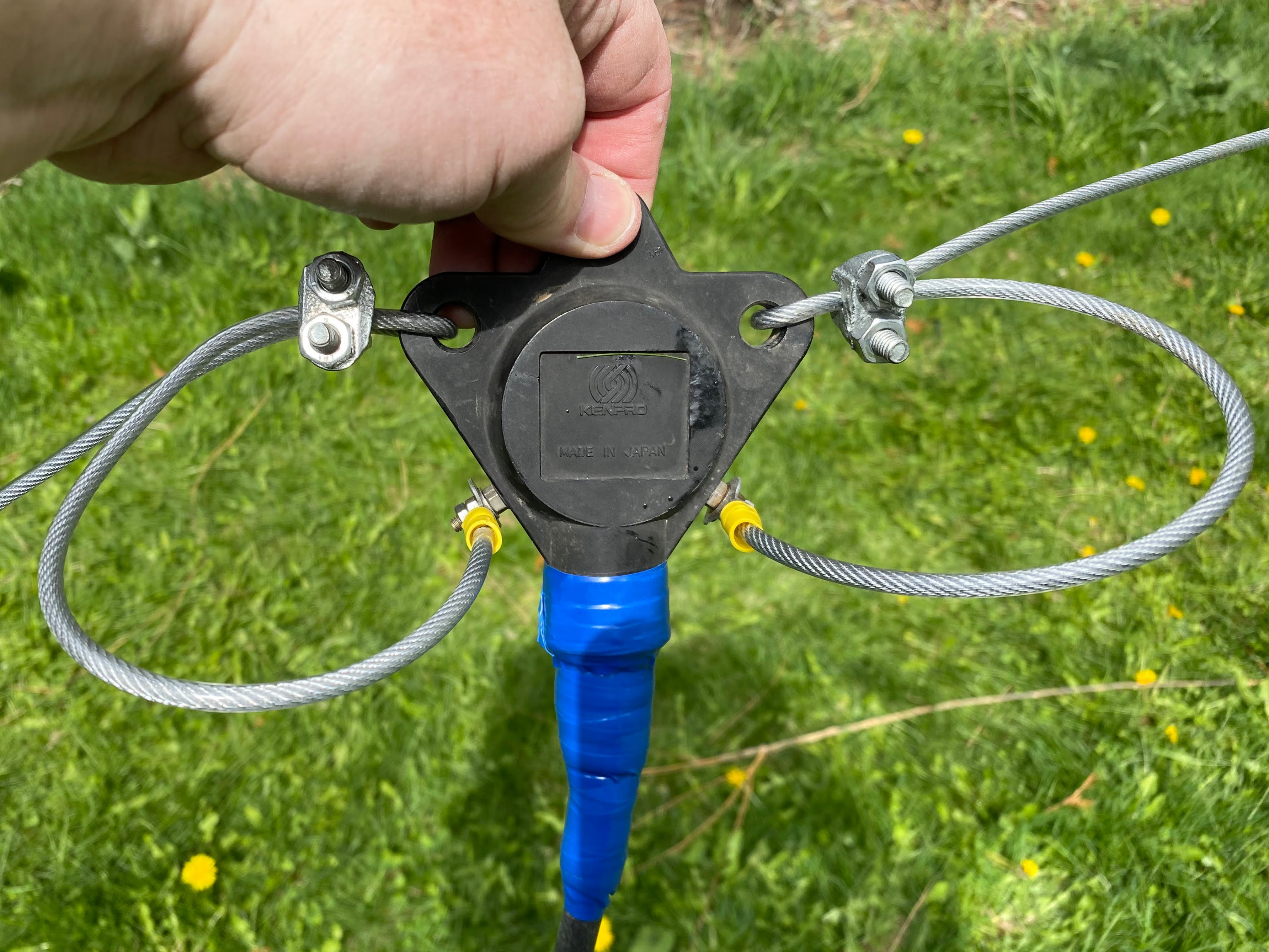
- Kenpro KA-50 1:1 balun (full specs below, also salvaged from another old antenna)
- 50' RG-8 coax cable with the UHF PL-259 connectors
- (2x) black plastic insulators
- (4x) wire cable clamps
- (2x) ring terminal connectors
- Silicone rubber weatherproofing tape
- Electrical tape
Specifications
Kenpro KA-50 (1:1 Balun) Freq Range : 1.8MHz-50MHz
Impedance: 50 ohm
Max power: 1kw CW - 2kw PEP (High Power Balun)
Ratio impedance: 1:1
The measurements below are for building a simple Dipole Antenna. The Wire Size can range from 16 AWG to 12 AWG. The larger the wire, the wider the bandwidth. The antenna is designed to be fed with 50 Ohm coax cable of almost any length with a Balun.
Place a 1:1 Balun on the antenna end of the Feedline. The Balun matches the Balanced Antenna into the Unbalanced Coax Cable. The balun will keep stray antenna currents off of the Feedline and help to keep stray RF out of the Radio Shack. If a Ferrite Balun is used, the balun needs to be rated at least twice the operating wattage to prevent the balun from overheating. This will help mitigate mismatches and stray RF due to using the antenna at frequencies other than what the antenna was specifically designed for.
Frequency: 14.175 MHz
Total Antenna Length ("L"): 33 Feet, 0.2 Inches
Element Length ("E"): 16 Feet, 6.1 Inches
Correct or incorrect I added 6 inches of extra cable at each end and marked the 16'1" measurements with a sharpie on the cable clear coating.
I soldered the ring terminal connectors to one end of each cable.
Then using 1 cable clamp for each cable I secured the cables to the KA-50 balun so the weight of the entire antenna and coax is not hanging from the ring terminals. As you can see in the photo below the clamps are close to the balun and an evened length loop connects to the screw terminals on the balun.